 In 1981, the Air Force developed a requirement
for an Advanced Tactical Fighter (ATF) as a new air superiority
fighter. It would take advantage of the new technologies in fighter
design on the horizon including composite materials, lightweight
alloys, advanced flight control systems, higher power propulsion
systems, and stealth technology. Air Force leaders believed these
new technologies would make aircraft like the F-15 and F-16
obsolete by the early 21st century. In 1985, the Air Force sent
out technical requests for proposals to a number of aircraft
manufacturing teams (Boeing/General Dynamics and Northrop/McDonnell
Douglas).
In 1981, the Air Force developed a requirement
for an Advanced Tactical Fighter (ATF) as a new air superiority
fighter. It would take advantage of the new technologies in fighter
design on the horizon including composite materials, lightweight
alloys, advanced flight control systems, higher power propulsion
systems, and stealth technology. Air Force leaders believed these
new technologies would make aircraft like the F-15 and F-16
obsolete by the early 21st century. In 1985, the Air Force sent
out technical requests for proposals to a number of aircraft
manufacturing teams (Boeing/General Dynamics and Northrop/McDonnell
Douglas).
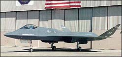
The Advanced Tactical Fighter (ATF) project was conceived in the early years of Reagan administration. It was pictured as being the aircraft which would replace the McDonnell Douglas F-15 Eagle in USAF service. The competitor were Lockheed with it's YF-22 and Northrop/McDonnel Douglas with it's YF-23.
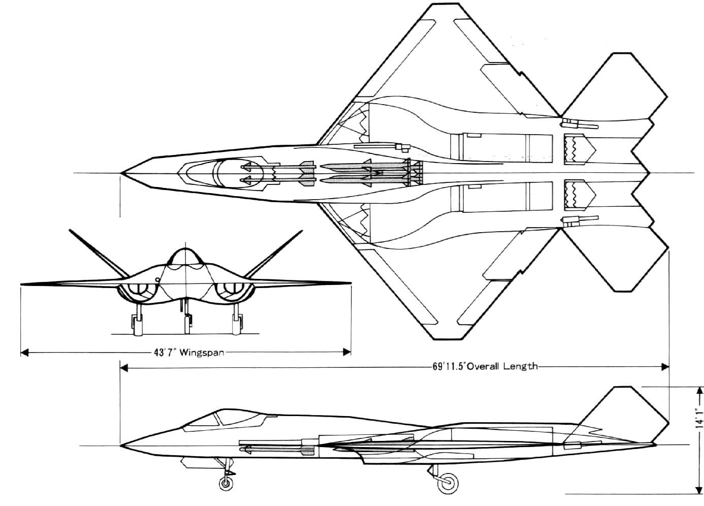
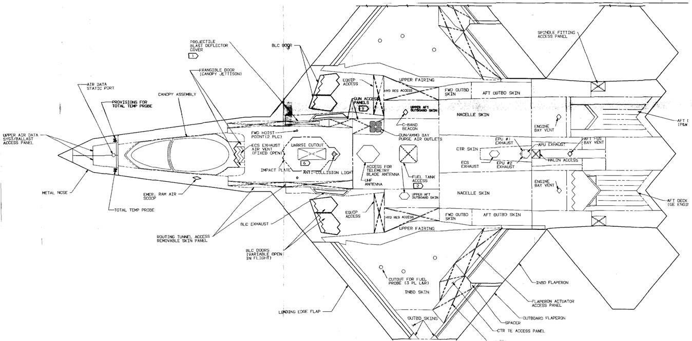
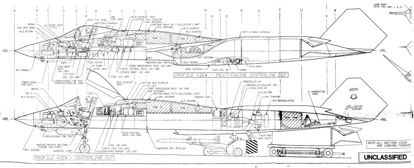
The body of the YF-23A is a blend of stealthy shapes and aerodynamic efficiency, hopefully providing a low radar cross section without compromising performance. The YF-23A was longer and more slender than the Lockheed YF-22A. The main load-bearing fuselage structure, measured from the stablizer to the front of the cockpit, is about 7 feet longer than the YF-22A. From the side, the profile of the YF-23A is reminiscent of that of the Lockheed SR-71. The general impression from other angles is that of a long, high forebody mounted between two widely-separated engine nacelles. The lengthwise variation in cross-sectional area is very smooth, minimizing transonic and supersonic drag. The forward section has a modified double-trapezoid cross section, one above the other in mirror image, with the aft region blending into a circular cross section and disappearing into the rear fuselage. The upper component of the engine box is dominated by two parallel engine nacelles that blend smoothly into the wing, each nacelle being of a modified trapezoidal cross section. The forebody has the cockpit, the nose landing gear, the electronics, and the missile bay. The YF-23 engine nacelles were larger than they would have been on the production F-23, since they had been designed to accommodate the thrust reversers originally planned for the ATF but later deleted.
Trapezoid-shaped air inlets are located underneath each wing, with the leading edge forming the forward lip of a simple fixed-geometry two-shock system. The placement of the intakes underneath the wings has the advantage in removing them from the sides of the fuselage so that a large boundary-layer scoop is not needed. Instead, the thin boundary layer which forms on the wing ahead of the inlet is removed through a porous panel and is vented above the wing. An auxiliary blow-in inlet door is located on each of the upper nacelles just ahead of the engine to provide additional air to the engines for takeoff or for low speeds. The inlet ducts leading to the engines curve in two dimensions, upward and inward, to shield the faces of the compressors from radar emitters coming from the forward direction.
The leading edge of the YF-23A's wing is swept back at 40 degrees, and the trailing edge is swept forward at the same angle. When viewed from above, the wing has the planform of a clipped triangle. On the YF-23A, every line in the planform is parallel to one or the other of the wing leading edges, which has become one of the guiding principles in stealthy design. The wing is structurally deep, and there is ample room for fuel inside the wing box.
The wing has leading-edge slats which extend over about two-thirds of the span. The trailing edge has a set of flaps inboard and a set of drooping ailerons outboard. In contrast to the Lockheed YF-22A, no speedbrake is fitted to the YF-23A.
The all-flying twin V-tails are set far apart on the rear fuselage. They are canted 50 degrees outwards in an attempt to avoid acute corners or right angles in elevation or front view. These all-flying tail sections are hinged at a single pivot. Their leading and trailing edges are parallel to the main wings but in a different plane. The all-flying canted tails double as shields for the engine exhaust in all angles except those immediately above or hehind the aircraft.
In the YF-23A, Northrop elected not to use thrust-vectoring for aerodynamic control. This was done in order to save weight and to help achieve better all-aspect stealth, especially from the rear. All controls are by aerodynamic surfaces. The V-tails work in pitch, roll, and yaw. The wing trailing edge controls provide roll control and lift augmentation, but they also function as speedbrakes and rudders. For straight line deceleration, the control system commands the outer ailerons to deflect up and the inboard flaps to deflect down, thus producing a decelerating force but creating no other moments. Yaw control can be provided by doing this on one side only.
There is a midair refuelling receptacle located on the upper fuselage behind the pilot's cockpit. Like the YF-22A, the YF-23A has a fly-by-wire system that controls the settings of the aerodynamic surfaces in response to inputs from the pilot.
The edge treatment is sustained on the fuselage afterbody, where a jagged-edged boat-tail deck fills in the gap between the two V-tails and blends the engine exhausts into the low-RCS planform. Unlike the YF-22A, the YF-23A does not use thrust vectoring. The exhaust nozzles are located well forward on the upper fuselage, between the tails, and are of the single expansion ramp type. There is one variable external flap on top of each nozzle, and the lower half of each nozzle is faired into a curved, fixed ramp. The engines exhaust into tunnels or trenches cut into the rear fuselage decking. These trenches are lined with head-resistant material, cooling the engine exhaust rapidly and making for a weaker IR source.
In the pursuit of stealth, all of the weapons carried by the F-23 were to have been housed completely internally. The forward section of the fuselage underbelly was flat, with a capacious weapons bay immediately aft of the nose gear bay. The bay could carry four AIM-120 AMRAAM air-to-air missiles. The missiles were to be launched by having the doors open and the missiles extend out into the airstream on trapezes. The missiles would then drop free and the motor would fire. The doors would then immediately shut, minimizing the amount of time that they were open and thus possibly causing more intense radar returns. It was planned that production F-23 would have had a stretched forebody, accommodating an extra missile bay for a pair of AIM-9 Sidewinders or ASRAAM air-to-air missiles in front of the AMRAAM bay. In addition, production F-23s would have carried a 20-mm M61 Vulcan cannon fitted inside the upper starboard fuselage just above the main weapons bay.
Evaluation:
The first YF-23, with Pratt & Whitney engines, supercruised
at Mach 1.43 on 18 September 1990, while the second, with General
Electric engines, reached Mach 1.6 on 29 November 1990. By comparison,
the YF-22 achieved Mach 1.58 in supercruise. The YF-23 was tested
to a top speed of Mach 1.8 with afterburners. The YF-23's weapons
bay was configured for weapons launch, and used for testing weapons
bay acoustics, but no missiles were fired. Lockheed fired AIM-9
Sidewinder and AIM-120 AMRAAM missiles successfully from its
YF-22 demonstration aircraft. PAV-1 performed a fast-paced combat
demonstration with six flights over a 10-hour period on 30 November
1990. Flight testing continued into December. The two YF-23s
flew 50 times for a total of 65.2 hours. The tests demonstrated
Northrop's predicted performance values for the YF-23. The YF-23
was stealthier and faster, but the YF-22 was more agile.
The two contractor teams submitted evaluation results with their proposals in December 1990, and on 23 April 1991, Secretary of the Air Force Donald Rice announced that the YF-22 was the winner.The Air Force selected the YF119 engine to power the F-22 production version. The Lockheed and Pratt & Whitney designs were rated higher on technical aspects, were considered lower risks, and were considered to have more effective program management. It has been speculated in the aviation press that the YF-22 was also seen as more adaptable to the Navy's NATF, but by 1992 the U.S. Navy had abandoned NATF.
Following the competition, both YF-23s were transferred to NASA's Dryden Flight Research Center at Edwards AFB, California, without their engines. NASA planned to use one of the aircraft to study techniques for the calibration of predicted loads to measured flight results, but this did not take place.
Location:
Both YF-23 airframes remained in storage until mid-1996, when
the aircraft were transferred to museums.YF-23A PAV-1, serial
number 87-0800, registration number N231YF, was on display as
of 2009 in the Research and Development hangar of the National
Museum of the United States Air Force near Dayton, Ohio.YF-23A
PAV-2, serial number 87-0801, registration number N232YF, was
on exhibit at the Western Museum of Flight until 2004,[34] when
it was reclaimed by Northrop Grumman and used as a display model
for a YF-23-based bomber.PAV-2 was returned to the Western Museum
of Flight and was on display as of 2010 at the museum's new location
at Torrance Airport, Torrance, California.
Possible revival:
In late 2004, Northrop Grumman proposed a YF-23-based bomber
to meet a USAF need for an interim bomber, for which the FB-22
and B-1R were also competing. Northrop modified aircraft PAV-2
to serve as a display model for its proposed interim bomber.
The possibility of a YF-23-based interim bomber ended with the
2006 Quadrennial Defense Review, which favored a long-range bomber
with a much greater range. The USAF has since begun the Next-Generation
Bomber program.
Number built/Converted : 2 (PAV-1 (87-800), PAV-2 (87-801))
Remarks : ATF; lost to YF-22
SPECIFICATIONS
Crew: 1 (pilot)
Length: 67 ft 5 in (20.60 m)
Wingspan: 43 ft 7 in (13.30 m)
Height: 13 ft 11 in (4.30 m)
Wing area: 900 ft2 (88 m2)
Empty weight: 29,000 lb (13,100 kg)
Loaded weight: 51,320 lb (23,327 kg)
Max. takeoff weight: 62,000 lb (29,000 kg)
Powerplant: 2 × General Electric YF120 or Pratt & Whitney YF119 turbofan, 35,000 lbf (156 kN) each Maximum speed: Mach 2.2+ (1,650+ mph, 2,655+ km/h) at altitude
Cruise speed: Mach 1.6 (1,060 mph, 1,706 km/h) supercruise at altitude
Range: over 2,790 mi (over 4,500 km)
Combat radius: 750–800 nmi (865–920 mi, 1,380–1480 km)
Service ceiling: 65,000 ft (19,800 m)
Wing loading: 54 lb/ft2 (265 kg/m2)
Thrust/weight: 1.36
Armament: (planned)
Internal gun 20 mm M61
Internal bay - 8x AIM-9 Sidewinder or 4x AIM-120 AMRAAM; A-G missiles "Have Dash 2", A-G missiles "Have Slick"
 |
 |
 |
 |
 |
 |
 |
 |
|
|